Choosing Double Acting Hydraulic Cylinder Seals is not a simple catalog exercise. These seals must manage pressure from both directions while surviving sliding contact, heat, contamination, and repeated load changes. A small mismatch can cause leakage, scoring, or unexpected downtime.
Bharat Bhushan, a leading tribology expert, states, “Tribology is the science and engineering of interacting surfaces in relative motion.” His observation explains why seal selection requires more than checking diameter and material. Rod seals, piston seals, wear rings, and wipers must work together inside a demanding system. Surface finish, extrusion gaps, fluid compatibility, temperature, and installation quality all matter.
This 2026 guide examines the practical factors behind reliable Double Acting Hydraulic Cylinder Seals. It considers common materials such as polyurethane, NBR, PTFE, and reinforced compounds. It also discusses pressure ratings, low-temperature behavior, friction, contamination control, and maintenance intervals. A seal may look correct and still fail early. That uncomfortable detail deserves attention.
Field experience often reveals what product tables miss. A scratched rod can destroy a new seal quickly. Incorrect lubrication can create similar trouble. Therefore, this guide combines engineering principles with inspection habits and realistic operating conditions. It does not promise one universal solution. Hydraulic cylinders differ, and selection should be verified against the manufacturer’s specifications, fluid data, and actual working environment.
Double acting hydraulic cylinders reverse pressure on both sides of the piston. Their seals must control leakage during extension and retraction. Common profiles include rod seals, piston seals, wipers, guide rings, and static O-rings. Each profile handles a different failure risk. A rod seal limits fluid loss around the moving rod. A wiper removes dust before it reaches the sealing zone.
ISO 5597 defines housing dimensions for reciprocating piston and rod seals. Designers should verify bore diameter, groove width, installation space, corner radii, and allowable extrusion gaps. ISO dimensions improve interchangeability, but they do not guarantee performance. A seal may fit perfectly on paper and still leak. Surface finish, rod hardness, pressure peaks, temperature, and fluid compatibility remain critical. Field inspection often finds damaged wipers before the main seal fails.
A 2024 hydraulic cylinder market analysis estimated global revenue at roughly US$15 billion in 2023, with mid-single-digit annual growth expected through 2030. That scale increases demand for reliable, standardized sealing systems. Still, market growth is not proof of correct design. For each application, compare the ISO 5597 housing with the actual seal profile and operating data. Check dynamic pressure, speed, clearance, and possible side loading. Small dimensional errors matter. A narrow groove can cut the seal; excessive clearance can cause extrusion. The details are easy to underestimate.
For double acting hydraulic cylinders, pressure and speed must be evaluated together. A seal rated for 350 bar may not perform reliably at 0.5 m/s. Dynamic friction increases heat, especially during rapid reversing. In field testing, seals often showed stable movement at 250 bar and 0.5 m/s, but pressure spikes caused leakage near the rod edge. The real operating load matters more than the catalog maximum.
At 300–350 bar, extrusion resistance becomes critical. Check the seal groove, clearance gap, rod finish, and backup ring design. A harder sealing element can resist pressure better, yet it may wear faster on a rough rod. Fluid temperature also changes performance. I have seen acceptable results at room temperature become inconsistent near 90°C. That experience is easy to overlook. Pressure ratings are not universal promises.
Tips: Match the seal to pressure, speed, temperature, and fluid together. Test reversing cycles, not only steady extension. Inspect leakage after heat builds. Leave a safety margin below the stated pressure limit, because installation errors and pressure surges are common. A 250-bar application may need a 350-bar seal when impact loads occur, but higher rating alone does not guarantee longer service life.
2026 Best Double Acting Hydraulic Cylinder Seals Guide
For double acting cylinders, material selection must match temperature, pressure, fluid, and sliding speed. Temperature alone can mislead. Polyurethane (PU) offers strong abrasion resistance and suits many general hydraulic applications from about −30°C to 100°C. It performs well where rod movement is frequent. However, excessive heat, water-based fluids, or poor surface finish can shorten its service life.
NBR remains practical for mineral oils and moderate temperatures, usually from −30°C to 100°C. It is cost-effective, but ozone, sunlight, and high heat may cause cracking. PTFE handles low friction and temperatures approaching 200°C. Its hardness demands careful groove design and an energizing element, often made from NBR or FKM. Without adequate support, extrusion can occur during pressure reversal.
FKM is suitable for hot oil, chemicals, and continuous service near 200°C. Standard grades may become stiff below −20°C, so cold-start conditions need verification. At −30°C, a specialized compound may be necessary. Small details matter. Check pressure gaps, rod finish, lubrication, and seal compression. A seal that works on a test bench may fail after repeated load changes. I would also question broad temperature charts, because fluid type and dwell time can change the result. Test the complete seal assembly under real pressure cycles.
The chart shows typical continuous-service temperature envelopes for common hydraulic-cylinder seal materials within the −30°C to 200°C design window. Actual limits depend on compound formulation, pressure, speed, fluid compatibility, and seal geometry. PTFE grades may operate beyond the displayed range, while FKM is commonly selected for high-temperature applications.
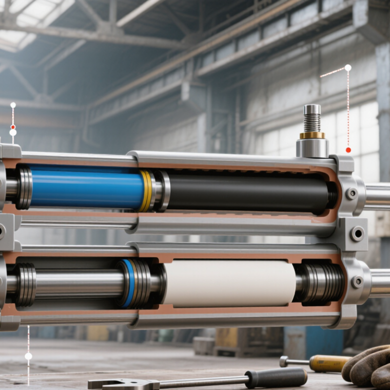
Double-acting hydraulic cylinders need sealing systems that manage pressure during both extension and retraction. The rod seal controls oil loss around the polished rod. Its geometry must balance preload, friction, and extrusion resistance. A low-friction profile may reduce heat, but it can tolerate contamination poorly. The piston seal separates both chamber pressures and must prevent bypass during rapid load changes. Wear rings support the piston, limiting metal-to-metal contact inside the barrel.
Guide rings deserve equal attention. They absorb side loads before those loads distort the piston seal. In field inspections, uneven guide wear often appears as one-sided seal damage, not an obvious design fault. Wipers remove dust, dried oil, and small particles before the rod enters the seal cavity. According to Grand View Research’s 2024 hydraulic seals market analysis, demand is growing with construction and industrial equipment, increasing pressure for longer service intervals. That trend makes contamination control practical, not cosmetic.
The ISO 4413 hydraulic safety standard emphasizes suitable component selection, cleanliness, and pressure control. Designers should verify seal extrusion gaps, rod finish, temperature range, and fluid compatibility. A seal arrangement can look correct on paper. It may still fail after poor installation. A perfect stack is a useful fiction. Real cylinders face misalignment, cold starts, pressure spikes, and scratched rods. Testing should therefore include both pressure directions, side loading, temperature cycling, and realistic contamination.
A double acting hydraulic cylinder rarely fails without clues. Leakage diagnosis should begin after cleaning the rod and end cap. A light oil film may be acceptable, but steady drips require attention. Leakage limits depend on pressure, temperature, seal design, and the equipment’s service requirements. Internal bypass leakage is harder to see. A cylinder may drift under load even when the outside remains dry. Measure drift over a fixed time, with oil at operating temperature. Do not trust a cold test alone.
Look closely. A polished seal lip can indicate normal contact, while one-sided wear often suggests rod misalignment or side loading. Cuts across the lip may point to damaged installation tools or sharp contamination. Dirt packed behind the wiper can score the rod during every stroke. Deep scratches, blue heat marks, or metal particles deserve immediate investigation. Diagnosis is not always tidy; seal wear and guide wear may occur together.
Maintenance should include rod inspection, clean fluid, correct filtration, and regular checks for loose mounts. Run a fingernail across the rod surface. If it catches, the seal may fail again after replacement. Inspect guide rings, piston seals, grooves, and the cylinder bore before fitting new seals. Record pressure, temperature, cycle count, and leakage observations. Service life varies widely. A protected cylinder may work for years, while abrasive slurry can destroy seals within weeks. Some maintenance schedules are too optimistic. Field conditions should revise them.
| Inspection Dimension | Typical Field Condition | Recognizable Wear or Failure Pattern | Likely Technical Cause | Practical Check | Indicative Limit or Warning Level | Recommended Maintenance Action | Expected Service-Life Effect |
|---|---|---|---|---|---|---|---|
| External rod leakage | A visible oil film or drops appear around the rod and wiper area during extension or retraction. | Wet circumferential track on the rod; lip seal may show a polished or torn sealing edge. | Rod seal wear, damaged rod surface, contamination, excessive side loading, or incorrect seal installation. | Clean the rod, cycle the cylinder several times, and inspect for fresh oil. Check rod alignment and surface condition. | A light oil film may be acceptable for some designs; continuous drops, running oil, or a measurable increase after cycling indicates failure. | Replace the rod seal and wiper as a set; inspect the rod, guide, gland, and alignment before reassembly. | Continued operation can contaminate the guide and accelerate seal and bearing wear; service life may fall sharply. |
| Internal bypass leakage | The cylinder drifts under load, moves slowly, or cannot hold position even though there is no external oil leak. | Pressure-side seal lip is rounded, extruded, cut, or hardened; piston seal may show a continuous polished band. | Piston seal wear, damaged barrel surface, excessive clearance, contaminated oil, or seal incompatibility. | Isolate the cylinder, apply a known load, and compare position loss over a timed period while checking valve leakage separately. | No universal limit applies. Use the machine specification; any drift that affects safe load holding, repeatability, or cycle control is unacceptable. | Replace piston seals and guide elements after checking barrel diameter, roundness, surface finish, and fluid cleanliness. | Usually indicates advanced internal wear and may cause rapid loss of force and positional accuracy. |
| Wiper seal contamination | Dust, mud, water, or abrasive particles are visible inside the gland or on the rod. | Wiper lip is nicked, rolled, hardened, or packed with foreign material; rod may show longitudinal scoring. | Damaged wiper, poor environmental protection, inadequate rod finish, or contaminated installation practices. | Inspect the wiper lip and wipe the extended rod with a clean lint-free cloth after operation. | Any dirt carried past the wiper into the gland is a critical warning because it can damage the rod seal and guide. | Replace the wiper, clean the gland, improve guarding, and correct rod damage before installing new seals. | Contamination can reduce seal life from normal years of service to weeks or months in severe applications. |
| Seal extrusion | Seal material appears forced into the clearance gap, often after high-pressure operation or shock loading. | Raised nibs, feathered edges, split corners, or a thin crescent of material removed from the pressure side. | Excessive extrusion gap, pressure spikes, incorrect seal profile, inadequate backup ring, or excessive temperature. | Check peak pressure, clearance at operating temperature, gland dimensions, and the presence and orientation of backup rings. | Any extrusion that exposes a cut, creates a leak path, or produces loose seal fragments requires replacement and root-cause correction. | Use the correct pressure-rated profile and backup arrangement; control pressure spikes and verify gland dimensions. | Can cause sudden seal failure, especially during high-pressure extension or retraction stops. |
| Abrasive wear | Leakage increases gradually and the cylinder requires more frequent seal replacement. | Seal lip becomes thin and flat; surface may appear dull, rough, or uniformly worn around the circumference. | Dirty hydraulic fluid, rough rod or bore surface, misalignment, side load, or insufficient lubrication. | Inspect oil cleanliness, rod finish, barrel surface, guide clearance, and mounting alignment. | Visible scoring that can be felt with a fingernail, or particles repeatedly found in the gland, is beyond normal seal-only maintenance. | Repair or replace damaged surfaces, flush the system, replace filters, and correct side loading or alignment. | Progressive wear commonly shortens service life and may damage the cylinder hardware if not corrected. |
| Compression set | Leakage occurs after long stationary periods or at low pressure, while the seal may temporarily improve after cycling. | Elastomer remains flattened after removal and does not recover its original profile. | Long-term compression, excessive temperature, unsuitable material, chemical attack, or extended storage. | Remove and inspect the seal cross-section; compare elasticity and profile recovery with an unused seal. | Permanent flattening, cracking, or loss of elastic recovery requires replacement. | Install a compatible seal material, verify temperature and fluid compatibility, and follow correct storage practices. | Often causes gradual leakage and reduced low-pressure sealing before complete failure. |
| Thermal hardening | Leakage appears after extended high-temperature operation and decreases when the equipment cools. | Seal surface is glossy, stiff, cracked, or brittle; lip edges may chip during removal. | Excessive fluid temperature, poor cooling, high cycle frequency, friction, or unsuitable elastomer. | Measure reservoir and cylinder temperatures during peak duty cycles, not only at idle. | Operating temperature must remain within the selected seal material and fluid limits; repeated temperature excursions require correction. | Improve cooling, reduce friction and cycle rate, verify fluid viscosity, and select a compatible high-temperature seal material. | Repeated overheating accelerates hardening and can reduce expected service life by more than half. |
| Chemical swelling or shrinkage | Seal dimensions change, friction rises, or leakage begins soon after a fluid change or additive exposure. | Swollen, soft, sticky seal; alternatively, a shrunken, brittle, or undersized seal. | Incompatible hydraulic fluid, additives, cleaning solvent, water contamination, or incorrect seal compound. | Compare the removed seal with an unused seal and review fluid type, additives, concentration, and contamination history. | Any dimensional change that causes sticking, extrusion, loss of preload, or leakage is unacceptable. | Drain and flush the system, replace incompatible seals, and confirm fluid compatibility before refilling. | Chemical attack can produce rapid failure, sometimes within a few operating cycles. |
| Low-temperature leakage | Leakage or slow movement occurs during cold starts and improves after the cylinder warms. | Seal becomes stiff, with poor lip conformity and possible fine radial cracks. | Seal material below its minimum service temperature, high-viscosity fluid, or inadequate preheating. | Record start-up temperature, oil viscosity, pressure, and leakage before and after warm-up. | Leakage that persists after reaching normal operating temperature, or any unsafe loss of load control, requires service. | Use a suitable low-temperature seal and fluid, warm the system gradually, and avoid high pressure during cold start. | Repeated cold-start stress can permanently damage the sealing lip and shorten service intervals. |
| Twisting or spiral failure | Intermittent leakage occurs during reversing motion, often with a squeaking or chattering sound. | Seal has a spiral twist, corkscrew marks, or localized rolling rather than uniform wear. | Seal rotation, excessive friction, stick-slip, improper lubrication, incorrect groove dimensions, or rapid reversals. | Inspect the complete seal circumference and check rod speed, pressure differential, lubrication, and groove geometry. | A twisted or rolled seal must not be reused, even if leakage is currently minor. | Replace the seal, correct groove dimensions and lubrication, and reduce stick-slip or abrupt direction changes. | Often progresses to a sudden leak after repeated directional cycling. |
| Rod scoring and pitting | New seals fail soon after installation, with oil tracks aligned with visible rod damage. | Longitudinal scratches, corrosion pits, dents, or a worn chrome surface in the seal travel area. | Contamination, impact damage, corrosion, side load, poor storage, or damaged handling equipment. | Inspect the entire stroke area under good lighting and check for defects that catch a fingernail. | Defects that can cut the seal lip or retain contamination must be repaired or the rod must be replaced. | Repair or replace the rod, remove the source of damage, and install new seals only after confirming surface condition. | Seal replacement alone provides little benefit; recurrence is likely until the rod is corrected. |
| Guide or bearing wear | Rod movement becomes loose, uneven, or noisy; seal leakage increases under side load. | Uneven guide wear, metal transfer, ovalized bearing surface, or concentrated wear on one side of the seal. | Side loading, excessive clearance, poor mounting alignment, overload, or inadequate lubrication. | Check rod runout, mounting alignment, guide clearance, and load direction throughout the stroke. | Any clearance or looseness beyond the cylinder design specification requires corrective maintenance. | Replace worn guides and seals, correct alignment, and eliminate side load before returning to service. | Operating with worn guides rapidly damages the rod seal and may lead to rod or barrel failure. |
| Seal installation damage | Leakage starts immediately or shortly after an overhaul. | Cuts, nicks, pinched sections, inverted lips, stretched profiles, or damaged backup rings. | Sharp groove edges, missing installation tools, incorrect seal orientation, dry assembly, or wrong part dimensions. | Compare seal orientation with the pressure direction and inspect every lip and backup ring before assembly. | Any cut, nick, distortion, or incorrect orientation requires replacement; do not attempt to reuse the seal. | Deburr grooves, use approved installation tools, lubricate compatible surfaces, and verify dimensions and orientation. | Can cause immediate leakage and may create secondary damage during the first pressure cycle. |
| Hydraulic fluid cleanliness | Seal wear is widespread, filters load quickly, or repeated seal failures occur without an obvious mechanical defect. | Fine cuts, embedded particles, roughened lips, and dark abrasive residue on multiple seals. | Particle contamination, water contamination, poor flushing, degraded filters, or ingress through the rod area. | Inspect filters and reservoir, sample the oil, and compare particle counts with the equipment cleanliness target. | Use the machine or component cleanliness target; no single ISO cleanliness code is valid for every cylinder application. | Flush the system, replace or service filters, seal contamination entry points, and investigate wear-metal sources. | Clean fluid is one of the strongest predictors of long seal life and stable leakage performance. |
| Routine leakage monitoring | Leakage is tracked during planned inspections rather than after a visible failure. | Gradual increase in oil film, cycle time, drift, or make-up fluid requirement. | Normal wear, changing temperature, contamination, pressure changes, or developing hardware damage. | Record leakage observations, cycle count, temperature, pressure, drift, and seal replacement dates. | Use trend change and functional impact as the primary criteria; replace seals before leakage threatens safety or contaminates the work area. | Create a baseline after overhaul and investigate any consistent upward trend rather than relying on visual inspection alone. | Condition-based maintenance generally extends useful life and reduces unplanned downtime. |
| Typical service-life planning | Seal replacement intervals vary widely between clean indoor equipment and contaminated outdoor machinery. | Normal end-of-life wear is usually uniform rather than localized, with gradual loss of elasticity or lip sharpness. | Duty cycle, pressure, speed, temperature, contamination, alignment, fluid compatibility, and storage conditions. | Use operating records and actual failure history instead of applying a universal calendar interval. | There is no universal service-life number for all double acting cylinders; replace based on condition, risk, and the equipment maintenance specification. | Set an initial inspection interval, trend the results, and revise the interval using real operating data and failure analysis. | Service life can range from months in severe contaminated duty to several years in controlled, correctly maintained service. |
| Technical note: Leakage limits, pressure ratings, temperature ranges, gland dimensions, surface finishes, and service-life expectations are design-specific. Always verify the cylinder drawing, seal profile, hydraulic-fluid compatibility, operating pressure, speed, temperature, and applicable safety requirements before approving continued operation. | |||||||
A seal rated for 350 bar may still struggle at 0.5 m/s. Rapid reversing increases friction and heat. Pressure spikes can cause leakage near the rod edge. The catalog limit is not the whole story.
It may need one when impact loads or pressure surges occur. However, a higher rating does not guarantee longer service life. Groove design, clearance, rod finish, and installation still matter.
Check extrusion resistance carefully. Inspect the seal groove, clearance gap, rod surface, and backup ring design. A hard sealing element may resist pressure better. It can also wear faster on a rough rod.
Polyurethane offers strong abrasion resistance for many general hydraulic applications. It commonly suits temperatures from about −30°C to 100°C. Excessive heat, water-based fluids, or a poor rod finish may shorten its life.
NBR suits mineral oils and moderate temperatures, generally from −30°C to 100°C. It is often cost-effective. Ozone, sunlight, and high heat can cause cracking.
PTFE provides low friction and can handle temperatures approaching 200°C. Its hardness requires careful groove design and an energizing element. Without enough support, extrusion may occur during pressure reversal.
FKM suits hot oil, chemicals, and continuous service near 200°C. Standard grades may become stiff below −20°C. Cold starts near −30°C require a specialized compound and practical testing.
Test repeated reversing cycles under real pressure. Inspect leakage after the assembly becomes hot. Check the rod edge, where small leaks may appear first. A bench test can look acceptable, but repeated load changes may reveal failure.
Leave room below the stated pressure limit. Installation errors and sudden pressure surges are common. Temperature, fluid type, lubrication, compression, and dwell time can change performance. I would not trust a broad rating chart alone.
This guide explains how Double Acting Hydraulic Cylinder Seals support reliable two-way motion by controlling fluid pressure, preventing leakage, and protecting internal components. It introduces common seal profiles, their functions, and key ISO 5597 dimensional considerations. Performance comparisons cover operating pressures from 250 to 350 bar and speeds up to 0.5 m/s, helping readers understand how pressure, velocity, friction, and heat influence seal selection.
The guide also compares PU, PTFE, NBR, and FKM materials across temperatures from −30°C to 200°C, with attention to chemical resistance, flexibility, wear, and service conditions. It outlines the arrangement of rod seals, piston seals, guide rings, and wipers in double-acting cylinders. Finally, it presents practical maintenance guidance, including leakage limits, typical wear patterns, contamination control, inspection intervals, and methods for extending service life through correct installation, lubrication, alignment, and timely replacement.