How to Choose the Right Hydraulic Drive System

Time:2026-10-19 Author:Henry
0%

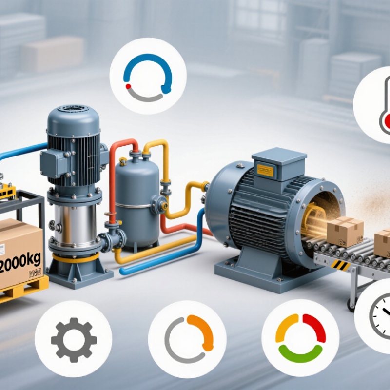
Choosing the right Hydraulic Drive System requires more than matching pressure and flow ratings. It demands a clear view of the machine, its workload, and its operating environment. A system lifting a 2,000-kilogram platform needs different priorities than one driving a mobile conveyor. Load changes, motor speed, duty cycle, ambient temperature, and available installation space all influence the final decision.

Start with measurable operating data. Record the required torque, peak pressure, continuous flow, response time, and expected service hours. Then examine the hydraulic pump, motor, valves, reservoir, filtration, hoses, and control strategy as one connected system. Efficiency matters. So does heat. Excessive heat can reveal undersized components, poor fluid selection, or unnecessary pressure losses. Small errors grow.

Experience from maintenance teams often exposes issues that catalogs overlook. A compact design may simplify installation but restrict cooling and future repairs. A high-performance component may offer excellent output while increasing contamination sensitivity or replacement costs. No selection method is perfect. Real machines operate in dust, vibration, cold starts, and imperfect maintenance conditions.

Reliable manufacturers provide verified performance curves, material specifications, installation guidance, and service recommendations. These documents support informed comparisons and reduce avoidable assumptions. Independent engineering review can also confirm whether the proposed system meets relevant safety and performance requirements. The best choice balances power, control, durability, efficiency, noise, and lifetime cost. It should perform well on paper and remain practical beside the machine, during commissioning, and years later in the field.
How to Choose the Right Hydraulic Drive System

Define the Power, Motion, and Operating Requirements

How to Choose the Right Hydraulic Drive System

Define the Power, Motion, and Operating Requirements

Start by defining the machine’s real power demand, not its advertised rating. Record load weight, required torque, shaft speed, acceleration, and running time. Measure the load.

A hydraulic drive must match the motion profile. A conveyor may need steady rotation, while a winch requires controlled starts and precise stopping. Note the direction changes, peak loads, and acceptable speed variation. Calculate continuous and intermittent power separately. A system sized only for average power may overheat during repeated lifting cycles. Do not guess.

Operating conditions often decide whether a design remains reliable. Check ambient temperature, fluid temperature, dust, moisture, installation space, and available maintenance access. Noise matters. A pump running near its limit may create heat, vibration, and unstable movement. Choose filtration, cooling, hose routing, and control valves around the actual duty cycle. These details are easy to overlook in a clean workshop.

Field experience also shows that paper calculations can mislead. Friction may increase as components age, and the load may not move evenly. Leave a practical safety margin, but avoid excessive oversizing. Oversized components can waste energy and reduce control quality. Test the system under realistic conditions, including cold starts and sudden load changes. Record pressure, temperature, and response time during commissioning. If the motion feels hesitant, the original assumptions need review.

Compare Hydraulic Drive Types and Circuit Configurations

How to Choose the Right Hydraulic Drive System

Compare Hydraulic Drive Types and Circuit Configurations

Selecting a hydraulic drive starts with the machine’s load, speed, and operating cycle. A fixed-displacement gear pump suits simple, steady-duty equipment with predictable flow demand. It is compact, economical, and easy to service. A vane pump usually operates more quietly. However, it may tolerate contamination less effectively than a rugged gear design. Variable-displacement piston pumps offer better efficiency when speed and load change frequently. They cost more and require cleaner oil.

Circuit configuration matters just as much as pump type. An open-circuit system returns fluid to the reservoir after actuation. This arrangement works well for lifting, clamping, and intermittent motion. A closed-circuit hydrostatic drive recirculates fluid between the pump and motor. It provides precise speed control and suits mobile traction applications. Parallel circuits let several actuators operate independently, but flow sharing can become uneven. Series circuits simplify some layouts, although pressure losses accumulate across each actuator.

In field inspections, heat often reveals poor matching before visible damage appears. A relief valve set too low can weaken movement. Set too high, it may stress components unnecessarily. Filtration, hose sizing, and return-line back pressure deserve equal attention. I have seen engineers choose a powerful pump while overlooking standby losses. That mistake can raise oil temperature during long shifts. The best comparison includes efficiency, control response, maintenance access, and failure consequences—not only maximum pressure. Small design assumptions matter.

How to Choose the Right Hydraulic Drive System - Compare Hydraulic Drive Types and Circuit Configurations

Drive Type or Circuit Configuration Typical Circuit Arrangement Operating Principle Speed and Torque Control Efficiency Characteristics Main Advantages Key Limitations Best-Fit Applications
Open-Circuit Fixed-Displacement Drive Reservoir → pump → directional or proportional valve → actuator → return filter → reservoir A pump draws fluid from the tank and sends it to the actuator. Flow returns to the reservoir after the work cycle. Speed is mainly controlled by pump flow and valve metering. Torque or force depends on pressure and actuator displacement. Moderate Simple layout, easy maintenance, relatively low initial cost, and straightforward heat management. Throttling losses can be significant when valves control speed. Continuous reversing may reduce efficiency. Machine tools, presses, material-handling equipment, clamps, lifts, and general industrial machinery.
Open-Circuit Variable-Displacement Drive Variable-displacement pump with pressure-compensated, load-sensing, or proportional control The pump changes displacement to match the required flow or pressure instead of delivering maximum flow continuously. Provides precise flow control and pressure regulation. Speed can be adjusted efficiently over a broad operating range. Moderate to high Lower energy consumption than fixed-displacement systems, reduced throttling, and good response to changing loads. Higher cost and greater control complexity. Correct commissioning is important for stability and noise control. Injection molding machines, industrial automation, mobile equipment, and systems with variable loads.
Closed-Circuit Hydrostatic Drive Variable-displacement pump and motor connected in a closed loop, with a charge pump and flushing circuit Fluid circulates directly between the pump and motor. A charge circuit replaces leakage and maintains loop pressure. Excellent bidirectional speed control, high starting torque, and smooth acceleration, deceleration, and reversing. High at matched operating points Compact power transmission, precise control, regenerative braking capability, and reduced flow through the main reservoir. Requires charge-pressure control, filtration, cooling, and careful contamination management. Circuit design is more complex. Travel drives, mobile machinery, winches, conveyors, and applications requiring frequent reversing.
Fixed-Displacement Pump and Motor Drive Open or closed circuit using fixed-displacement pump and fixed-displacement motor Each shaft revolution moves a nearly constant fluid volume. System output changes primarily with pump speed and pressure. Simple on/off or proportional valve control. Speed range and control precision are limited unless additional control elements are used. Moderate Robust, economical, easy to understand, and suitable for steady-duty operation. Limited efficiency at partial load and less flexible speed control. Excess flow may be converted into heat. Fans, augers, basic conveyors, agricultural implements, and constant-speed auxiliary functions.
Variable-Displacement Pump and Motor Drive Open or closed circuit with adjustable pump displacement, adjustable motor displacement, or both Displacement is varied to control flow, speed, torque, or the relationship between speed and available output torque. Very wide speed range, high torque at low speed, and flexible operating modes such as constant power or constant torque. High when correctly sized Strong controllability, efficient power matching, and suitability for changing load and speed requirements. Higher purchase cost, more sensitive control requirements, and greater need for clean fluid and accurate adjustment. Hydrostatic transmissions, heavy mobile equipment, drilling systems, and variable-speed industrial drives.
Meter-In Speed-Control Circuit Flow-control valve installed in the inlet line to the actuator The valve restricts incoming flow to regulate actuator speed while the actuator is extending or rotating in the driven direction. Good control when the load tends to resist motion. Speed depends on valve setting and load conditions. Low to moderate Simple, inexpensive, and effective for resistive loads with predictable force requirements. Can cause instability or runaway motion with overrunning loads. Restricted flow creates heat and wastes energy. Clamping, pressing, and actuator movements where the load opposes the motion.
Meter-Out Speed-Control Circuit Flow-control valve installed in the actuator outlet line The valve controls the rate at which fluid leaves the actuator, creating back pressure that helps regulate motion. Stable speed control for many resistive and overrunning loads, provided pressure limits are respected. Low to moderate Prevents uncontrolled actuator acceleration and is generally more stable than meter-in control for overrunning loads. Excess back pressure may increase heat generation and reduce available actuator force. Vertical cylinders, lowering loads, drilling feeds, and actuators with a tendency to run ahead.
Pressure-Compensated Flow-Control Circuit Pressure-compensated flow-control valve with an upstream or downstream compensator The compensator maintains a nearly constant pressure drop across the metering orifice, helping maintain flow as load pressure changes. More consistent actuator speed than a basic throttle valve, especially under varying loads. Moderate Improved repeatability, better load variation tolerance, and relatively simple implementation. Still produces throttling losses and may be less efficient than pump-controlled flow regulation. Multi-actuator machines, production equipment, and systems requiring repeatable but moderate-speed control.
Load-Sensing Circuit Variable-displacement pump controlled by a load-pressure signal and a standby-pressure margin The pump supplies only the flow demanded by the active function while maintaining a controlled pressure margin above load pressure. Responsive proportional control with good speed regulation across changing loads and multiple functions. High Reduced unloaded losses, improved fuel or electrical efficiency, and effective flow sharing between functions. Requires correctly tuned controls, suitable signal lines, and careful management of pressure margin and response time. Mobile machinery, multi-function handling equipment, and industrial systems with frequently changing demand.
Pressure-Compensated Pump Circuit Variable-displacement pump with a pressure compensator set to a defined maximum or standby pressure The pump reduces displacement as system pressure approaches the compensator setting, limiting unnecessary flow at high pressure. Good force or torque control with moderate speed control. Flow availability depends on pump capacity and pressure demand. Moderate to high Protects the system from excessive pressure and reduces some energy loss during stalled or low-flow conditions. Can operate at higher pressure than required by the load, causing avoidable energy consumption compared with load sensing. Presses, lifting systems, machine tools, and applications with relatively stable pressure requirements.
Regenerative Circuit Actuator outlet flow is routed back to the actuator inlet during a selected part of the stroke Returning fluid combines with pump flow to increase actuator extension speed, usually at the expense of available force. High extension speed during low-load portions of a cycle; normal hydraulic operation resumes when higher force is needed. Moderate Shorter cycle times, reduced pump flow requirement, and efficient use of available actuator flow. Reduced extension force, potential control transition issues, and increased sensitivity to load changes. Press cycles, material handling, machine slides, and applications with fast approach and slower working strokes.
Accumulator-Assisted Drive Hydraulic accumulator connected to the supply, return, or dedicated auxiliary circuit The accumulator stores pressurized fluid and releases it during peak demand, absorbs pressure pulses, or provides emergency power. Supports rapid transient flow and peak-power response; actuator speed depends on accumulator pressure and available volume. High for peak-demand support Reduces pump peak size, improves response, recovers energy in suitable systems, and can provide limited operation during power loss. Requires pre-charge checks, suitable safety protection, and correct sizing for pressure, temperature, and cycle frequency. High-cycle machinery, shock absorption, emergency lowering, pulsation reduction, and peak-flow applications.
Electrohydraulic Proportional Circuit Electronic controller, sensors, proportional valves, and hydraulic power unit Electrical command signals regulate hydraulic flow or pressure through proportional valves and feedback controls. Fine speed, force, and position control; closed-loop feedback can improve accuracy and repeatability. Moderate to high Flexible automation, programmable motion profiles, remote control, diagnostics, and integration with machine-control systems. Higher system complexity, electrical dependency, and greater sensitivity to tuning, wiring, electromagnetic compatibility, and contamination. Robotics, automated production lines, test systems, precision handling, and synchronized multi-axis machinery.

Selection should consider required speed, torque or force, duty cycle, load profile, controllability, operating pressure, heat generation, maintenance capability, and total energy consumption.

Match Pressure, Flow, and Torque Ratings to the Application

How to Choose the Right Hydraulic Drive System

Match pressure, flow, and torque ratings to the real application, not the ideal brochure condition. Pressure creates actuator force, while flow controls speed. Motor torque depends on pressure difference, displacement, and efficiency. A practical estimate is T = Δp × displacement ÷ (2π × efficiency). Use actual efficiency, not a perfect 100% assumption.

The U.S. Department of Energy’s pumping-system guidance indicates that pumping equipment can consume 20–60% of industrial motor electricity. Hydraulic losses make correct sizing important. Select a continuous pressure rating above the normal load, then check peak pressure during starts, jams, and rapid deceleration. Match pump displacement and operating speed to required flow. A system needing 80 L/min should not rely on a valve to waste 30 L/min continuously. That approach works, but it creates heat. Temperature may become the hidden failure.

Tips: Record pressure and flow at the machine, not only at the power unit. Confirm torque at the shaft after mechanical losses. Check oil viscosity at both cold start and operating temperature. ISO 4413 also emphasizes safe pressure control and energy isolation. Leave a sensible margin, perhaps 10–20%, but avoid extreme oversizing. Bigger is not automatically better. Field measurements often reveal assumptions that looked reasonable on paper were wrong.

How to Choose the Right Hydraulic Drive System

Match the hydraulic motor and control system to the application's continuous pressure, flow, and output torque requirements. The representative ratings below are based on typical operating ranges for industrial and mobile hydraulic equipment.

How to read the chart: Pressure determines the force available in the hydraulic circuit, flow determines motor speed, and torque determines the turning force at the output shaft. Select a system with ratings above the application's continuous requirements while allowing suitable margin for starting loads and peak conditions.

Evaluate Control Methods, Efficiency, and Environmental Conditions

How to Choose the Right Hydraulic Drive System

Evaluate Control Methods, Efficiency, and Environmental Conditions

Choosing a hydraulic drive system starts with its control method, not its maximum pressure. Proportional valves offer smooth speed changes for conveyors, lifts, and forming equipment. Servo control can deliver tighter positioning, but it usually demands cleaner oil and careful tuning. Simple directional valves may be enough for fixed-speed movement. Keep it practical. A complex control scheme can create maintenance problems when operators lack training.

Efficiency depends on more than pump capacity. Check pressure losses across valves, hoses, filters, and fittings. A small restriction can generate heat during long operating cycles. Variable-displacement pumps may reduce wasted flow, especially when demand changes frequently. Measure actual cycle times and oil temperature instead of trusting catalog figures. In commissioning work, real loads often differ from early calculations. That gap deserves attention.

Environmental conditions can change the correct design. Dusty areas require protected components and reliable filtration. Outdoor systems may need seals and fluids suited to temperature swings. In humid locations, exposed metal surfaces can corrode quickly. Near washdown zones, connectors and enclosures need suitable protection ratings. Noise also matters in occupied workshops; lower pump speed and isolation mounts can help. Do not overlook access. A highly efficient system becomes a poor choice if filters are difficult to replace or leaks are hard to inspect.

Verify Safety, Maintenance Needs, and System Compatibility

Choosing a hydraulic drive system begins with safety, not maximum pressure. ISO 4413:2010 requires risk reduction, pressure control, and protection against unexpected movement. Check relief valves, hose ratings, guards, and emergency isolation points. A small leak can become a serious injection injury.

Maintenance needs equal attention. The U.S. Bureau of Labor Statistics reported 2.6 million nonfatal workplace injuries in private industry during 2023. Hydraulic equipment adds stored energy, hot fluid, and contamination risks. Create inspection intervals for filters, seals, fittings, and fluid cleanliness. Keep records. Missed records create blind spots.

Compatibility is often underestimated. Confirm the pump, motor, actuator, reservoir, valves, and control system share suitable pressure, flow, temperature, and fluid specifications. Review the manufacturer’s technical data, then test under realistic loads. ISO 4406 cleanliness codes can guide contamination control. Do not assume a replacement component will fit safely. It may fit mechanically, yet fail under heat or pressure. Field experience often reveals this gap. Leave room for doubt, and verify twice.

FAQS

How do I choose a hydraulic pump type?

Match the pump to load, speed, and operating cycle. A fixed-displacement gear pump suits steady duties. A variable-displacement piston pump handles changing loads more efficiently. I might choose too much capacity without checking standby losses.

When is a vane pump a practical choice?

A vane pump usually runs more quietly than a gear pump. It can suit equipment where lower noise matters. However, contamination may affect it more severely. Clean oil remains important.

What is the difference between open and closed circuits?

An open circuit returns fluid to the reservoir after actuation. It suits lifting, clamping, and intermittent movement. A closed circuit recirculates fluid between the pump and motor. It provides precise speed control for traction applications.

What are the benefits and risks of parallel circuits?

Parallel circuits allow several actuators to work independently. They can support flexible machine movement. However, flow sharing may become uneven. One actuator may respond faster than another.

What should I check when setting a relief valve?

A setting that is too low can weaken movement. A setting that is too high may stress components unnecessarily. Confirm pressure limits for every connected component. Do not rely on guesswork.

How can I identify poor hydraulic system matching?

Check oil temperature during realistic operating cycles. Excess heat can reveal poor matching before visible damage appears. Review pump efficiency, control response, hose sizing, and return-line back pressure. Maximum pressure alone is not enough.

What safety features should a hydraulic drive system include?

Review relief valves, hose ratings, guards, and emergency isolation points. Protect against unexpected movement and stored energy. A small leak can cause a serious injection injury. Risk reduction must guide the design.

How should hydraulic system maintenance be organized?

Set inspection intervals for filters, seals, fittings, and fluid cleanliness. Record each inspection and corrective action. Missed records create blind spots. Check contamination using suitable cleanliness guidance, such as ISO 4406 codes.

How can I confirm component compatibility?

Verify pressure, flow, temperature, and fluid specifications across all components. Include the pump, motor, actuator, reservoir, valves, and controls. A replacement may fit mechanically but fail under heat or pressure. Test under realistic loads. Verify twice.

Conclusion

Choosing the right Hydraulic Drive System begins with clearly defining the machine’s power demand, movement pattern, speed range, load characteristics, and operating cycle. These requirements help determine whether a fixed or variable displacement system, open or closed circuit, and other hydraulic configurations are most suitable. Pressure, flow, torque, and response ratings should be matched carefully to the application to ensure reliable performance without unnecessary energy use or component stress.

The selection process should also consider control methods, efficiency, temperature, dust, moisture, noise, and available installation space. Proportional controls or simpler valve arrangements may be chosen according to the required precision and budget. Before finalizing the system, verify safety features, maintenance access, filtration requirements, fluid compatibility, and integration with existing mechanical and electrical equipment. A well-matched design improves productivity, reduces downtime, and supports long-term operational reliability.


Henry

Henry

Henry is a dedicated marketing professional with a profound expertise in the company's offerings. With years of experience in the industry, he possesses an impressive understanding of the market dynamics and consumer behaviors that drive success. Henry is committed to sharing his insights through......