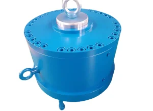
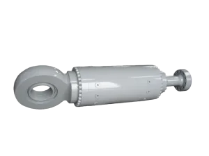
Engineered to deliver millimetric position accuracy and continuous high-pressure stability across cement grinding, steel rolling, and heavy industrial automation.
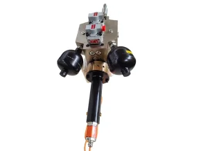
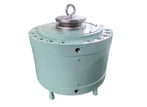
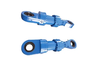
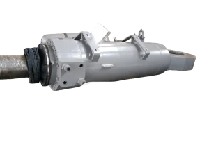
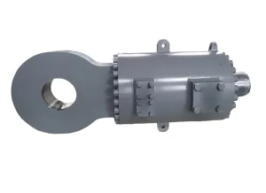
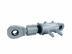
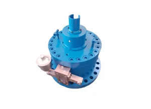
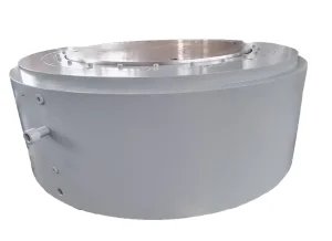
As modern heavy industrial machinery transitions toward automated, high-duty-cycle operation, maintaining hydraulic integrity has become the definitive bottleneck for operational uptime and energy efficiency.
In heavy processing plants such as cement grinding facilities, steel rolling mills, and mining extraction sites, hydraulic failure translates directly to crippling financial loss. A single undetected valve erosion or internal cylinder bypass leak can result in operational shutdowns costing excess of $50,000 per hour.
Precision hydraulic testing systems enable predictive health monitoring, allowing maintenance engineers to measure real-time volumetric efficiency ($\eta_v$), dynamic pressure drop, and fluid contamination levels before mechanical seize-up occurs.
Modern high-performance servo actuators and proportional valve banks require extreme fluid purity, typically targeting ISO 4406 cleanliness standards of 16/14/11 or cleaner. High-pressure hydraulic testers integrate inline laser particle counters and moisture sensors to detect micro-abrasives before they destroy clearance seals.
By continually monitoring fluid health under actual operating temperatures (up to 90°C) and extreme working pressures (up to 700 bar), hydraulic testers extend component lifespan by up to 300%.
For international buyers, OEM machinery builders, and field maintenance contractors, verifying original equipment performance metrics requires traceable, laboratory-grade diagnostic instruments.
High-quality hydraulic testers provide accurate dynamic response curves, hysteresis loop data, and holding force measurements, enabling transparent compliance reporting according to European CE standards and ISO 9001 quality guidelines.
Our engineering roadmap integrates multi-sensor telemetry, dynamic loading valves, micro-clearance leakage quantification, and AI edge computing to setting new benchmarks in fluid power diagnostics.
Traditional flowmeters experience substantial measurement drift when hydraulic fluid temperature fluctuates, causing viscosity shifts. Our advanced hydraulic testers employ dual-pulse pick-off turbine flow transducers combined with integrated Pt100 RTD sensors. Embedded algorithm calibration automatically adjusts for oil viscosity variations across 10 to 100 cSt, ensuring a linear measurement accuracy of ±0.25% of reading.
To capture rapid transient pressure spikes, water hammer phenomena, and high-frequency valve hunting, our diagnostic consoles utilize piezoresistive silicon pressure sensors featuring microsecond response rates (<1 ms). Capable of sampling at up to 10 kHz, these units capture peak transient pressures up to 700 bar without sensor saturation, preventing fatigue damage in severe-duty hydraulic circuits.
For specialized low-friction servo cylinders and clearance seal hydraulic actuators, standard external visual inspections cannot detect internal fluid bypass. Our diagnostic software isolates the cylinder's rod and cap chambers under locked-load condition, measuring pressure decay rates down to 0.01 bar/min. This precise quantification identifies seal micro-wear months before total operational failure.
Next-generation hydraulic testing units feature onboard ARM-Cortex edge processing units loaded with predictive maintenance neural networks. By evaluating real-time pump flow curves ($Q$ vs $P$) against historical baseline profiles, the edge processor automatically flags swashplate wear, valve plate cavitation, and internal motor slip in real time.
| Diagnostic Parameter | Standard Portable Unit | Heavy Industrial Benchtop | AI-Enabled Servo Test Stand |
|---|---|---|---|
| Working Pressure Range | 0 – 420 Bar (6000 PSI) | 0 – 600 Bar (8700 PSI) | 0 – 700 Bar (10,000 PSI) High Dynamic |
| Flow Measurement Range | 10 – 400 L/min | 20 – 800 L/min | 0.5 – 1200 L/min Dual Turbine |
| Transducer Accuracy | ±0.5% Full Scale | ±0.3% Reading | ±0.15% Reading (Calibrated) |
| Sampling Rate (Data Acquisition) | 1 kHz | 5 kHz | 10 kHz High Frequency |
| Fluid Temperature Range | -20°C to +100°C | -30°C to +120°C | -40°C to +150°C (Pt100 Integrated) |
| Cleanliness Monitoring | Manual ISO Dipstick | Inline Optical Particle Counter | Triple Laser ISO 4406 / NAS 1638 Sensor |
| Data Connectivity | USB / SD Card Export | Ethernet Modbus TCP / RS485 | IoT Cloud Telemetry / OPC-UA / CANbus |
From cement grinding mills to continuous metallurgical casters, specialized hydraulic testing protocols are tailored to the unique mechanical stresses and environmental hazards of each sector.
In cement manufacturing lines, vertical roller mills (VRM) such as Loesche LM, UBE UM, Pfeiffer MPS, and FLSmidth ATOX rely on immense hydraulic loading pressure to crush limestone and clinker.
Testing Task: High-pressure hydraulic testers evaluate tensioning cylinder accumulation rates, proportional directional valve response, and accumulator nitrogen pre-charge pressure without disassembling the heavy mill framework during scheduled maintenance shutdowns.
Roller Press Support: For high-pressure grinding roll (HPGR) units (e.g., Chengdu Leejun CLF, CITIC Heavy Industries, and HCRI series), hydraulic testers perform precise dual-cylinder synchronization checks, mitigating asymmetric roller tilting and bearing destruction.
Continuous steel casting lines and hot/cold rolling mills operate under extreme ambient heat, heavy shock loads, and high cycle frequencies.
Testing Task: High-speed diagnostic equipment tests Automatic Gauge Control (AGC) servo cylinders and hydrostatic support servo systems. Testers verify dynamic dynamic frequency response up to 50 Hz and measure micro-leakage in low-friction seals under severe thermal radiation conditions.
Rotary Kiln & Grate Coolers: Hydraulic testers verify hydraulic thrust roller systems and grate cooler push-bar stroke consistency, preventing heat distortion and mechanical binding.
Large-scale mining excavators, stacker-reclaimers, and marine deck machinery operate in remote, hostile environments prone to sand, salt spray, and extreme sub-zero or tropical temperatures.
Testing Task: Portable field hydraulic testers allow field engineers to quickly troubleshoot main hydraulic pumps, slew drives, and harrow cylinder circuits under field load conditions.
Preventive Diagnostics: By conducting routine load testing during oil changes, technicians detect pump cavitation, relief valve setting drift, and internal motor bypass before catastrophic field breakdown occurs in remote locations.
Situated in Changzhou, Jiangsu Province—China’s premier high-end hydraulic manufacturing hub—our production facility leverages complete supply chain integration to deliver uncompromised precision at highly competitive cost structures.
Our manufacturing complex spans over 20,000 m², encompassing specialized raw forging, deep-hole boring, CNC honing, heat treatment, hard-chrome plating, and sensor integration all within a 15-kilometer radius.
This localized industrial density minimizes logistic lead times for raw materials, ensuring standard component turnaround within 5 working days and complete custom hydraulic tester manufacturing within 3 to 4 weeks.
Quality begins with machining accuracy. Our facility is equipped with imported 5-axis CNC machining centers, high-precision cylindrical grinders, and horizontal honing machines from Germany and Japan.
Bore tolerances are routinely finished to H7/H8 standards with surface roughness below $Ra\ 0.1\ \mu m$, guaranteeing that hydraulic test manifolds and diagnostic valve blocks achieve leak-free operation under 700 bar pressure.
Every hydraulic tester, manifold block, and custom testing cylinder undergo 100% full-load hydrostatic testing before export packaging. Tests are conducted at 1.5 times the maximum rated working pressure for a minimum holding duration of 30 minutes.
Each unit is issued a digital test certificate detailing flow vs pressure calibration curves, sensor accuracy verification, and ISO 4406 fluid cleanliness scores.
Serving industrial clients across 30+ countries, we ensure strict compliance with global engineering standards, international metrology calibration, and full lifetime technical support.
Our hydraulic testers and customized testing manifolds comply with European CE Machinery Directive (2006/42/EC) and Pressure Equipment Directive (2014/68/EU). Quality management systems are audited and certified to ISO 9001:2015.
All electrical diagnostic consoles feature IP65/IP67 ingress protection, CE-marked EMC shielding, and explosion-proof ATEX options for chemical and mining environments.
Flow sensors, pressure transducers, and thermal probes installed in our diagnostic units are calibrated against reference standards traceable to NIM (National Institute of Metrology) and NIST guidelines.
Export units are delivered with universal metric/NPT adapter kits, multi-language diagnostic software interfaces (English, Spanish, German, Russian), and comprehensive recalibration protocols.
We provide global lifecycle technical support, including remote video diagnostic assistance, rapid seal spare part dispatch via air freight, and on-site engineering assistance for complete hydraulic system commissioning.
Our engineering support team directly reviews customer system schematics, providing customized diagnostic procedures and replacement component drawings to ensure zero fitment risk.
Detailed technical answers regarding hydraulic testing methodologies, diagnostic calibration, component isolation, and industrial maintenance best practices.
To accurately isolate pump degradation from relief valve leakage, the hydraulic tester is connected inline immediately downstream of the pump outlet, upstream of the relief valve. With the tester's load valve open, initial flow ($Q_{\text{open}}$) is recorded at low pressure. The load valve is then incrementally closed to increase system pressure to working load.
If flow drops significantly as pressure rises, the pump swashplate or valve plate has suffered volumetric wear ($\eta_v = Q_{\text{load}} / Q_{\text{open}}$). If flow remains steady until the relief valve cracking threshold is reached and then drops suddenly, the relief valve seat is worn or improperly set. Our digital diagnostic software plots this $Q/P$ curve automatically in real time.
Clearance seal servo cylinders feature micro-inch tolerances between piston and bore to minimize friction in high-frequency closed-loop systems. To measure internal bypass, the cylinder rod is mechanically locked at mid-stroke. High pressure is applied to the cap-end port while the rod-end port is connected directly to the hydraulic tester’s precision micro-flow sensor.
The flow sensor measures fluid bypass passing across the piston clearance gap. Measuring this leakage across controlled pressure steps (e.g., 50, 100, 200, 315 bar) allows engineers to calculate radial gap growth due to bore erosion against original factory baseline tolerances.
Fluid viscosity alters turbine rotor drag and differential pressure across flow orifices. High-quality hydraulic testers solve this by integrating a fast-response Pt100 RTD temperature probe directly into the turbine flow block.
The internal processor utilizes a multi-point viscosity matrix (storing kinetic viscosity curves for ISO VG 32, 46, 68, and 100 oils). The system calculates real-time fluid density and viscosity at the measured temperature, applying dynamic polynomial correction equations to maintain turbine accuracy within $\pm0.25\%$ across $15^\circ\text{C}$ to $90^\circ\text{C}$.
Operating diagnostic equipment at extreme pressures (up to 700 bar) presents severe fluid injection and burst hazards. Our hydraulic testers incorporate a multi-layer safety architecture:
Yes. We specialize in engineering customized industrial hydraulic test consoles specifically configured to simulate the exact mounting geometry, stroke lengths, and dynamic pressure profiles of OEM grinding equipment.
Whether testing loading cylinders for Loesche LM, UBE UM, Pfeiffer MPS vertical mills, or high-pressure cylinders for Leejun and CITIC roller presses, our test stands feature customizable mounting fixtures and automated software scripts that mirror OEM operational duty cycles.
For heavy industrial field diagnostics, we recommend annual recalibration (every 12 months) under standard operating conditions. For continuous high-duty lab test stands running 24/7 in ISO 9001 certified plants, bi-annual recalibration (every 6 months) is advised.
Recalibration involves verifying turbine transducer pulse counts against master flowmeters, zero-point calibration of piezoresistive pressure sensors, and RTD probe verification against ice-point and boiling-point temperature standards.
Explore our full line of cement mill cylinders, hydrostatic support servo actuators, roller press cylinders, and heavy equipment hydraulic components.